- Insights
- Calibrating the sensors behind your cleanroom pressure cascade
HVAC & cleanrooms
Calibrating the sensors behind your cleanroom pressure cascade
Differential pressure transmitters, room monitors and door alarms decide whether your cascade is proven or just assumed. Here is how to calibrate the whole chain, from the sensing port to the BMS or EMS screen.
Why the cascade depends on a few small sensors
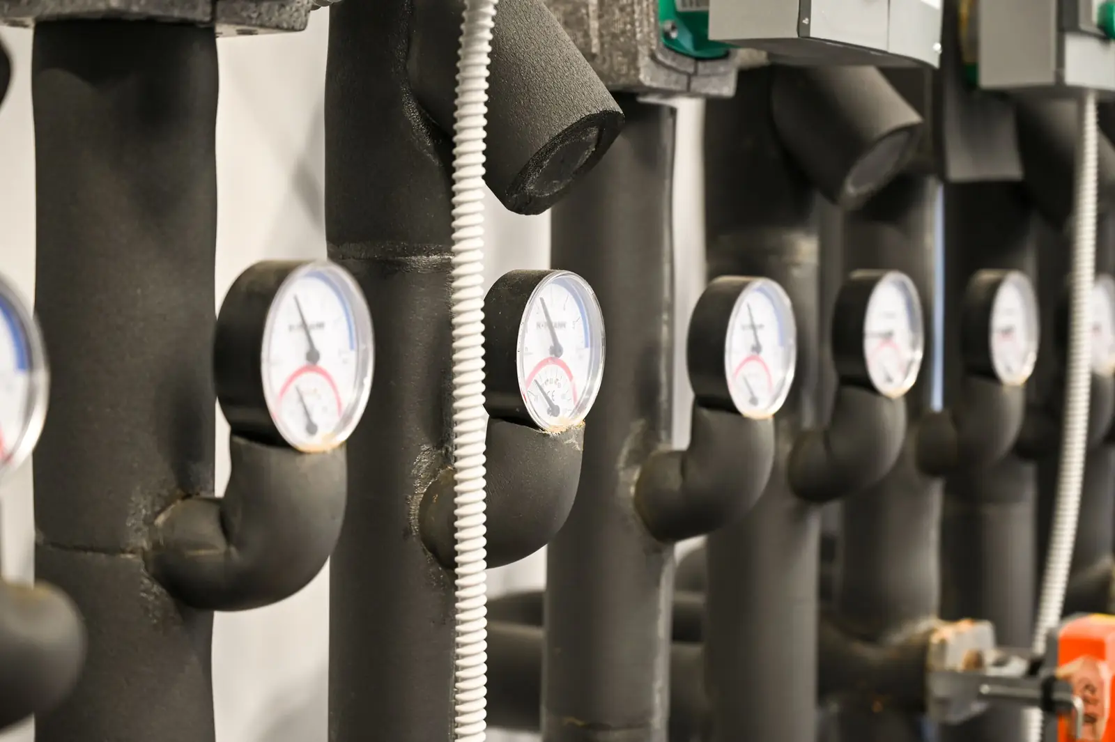
A cleanroom pressure cascade keeps air moving from cleaner spaces to less clean ones, so that contamination is pushed out rather than drawn in. The design lives in the air handlers, dampers and room envelope, but the proof lives in a handful of instruments: the differential pressure transmitters between rooms, the room pressure monitors at the doors, the alarms, and the readout in your building or environmental monitoring system.
Regulators expect that proof. EU GMP Annex 1 gives a guidance value of at least 10 pascals between adjacent rooms of different grades, and expects indicators of the pressure difference between cleanrooms. Differences identified as critical should be monitored and recorded continuously, with a warning system that alerts operators when the difference drops below its set limit. FDA’s aseptic processing guidance gives a similar example, a positive differential of at least 10–15 pascals between adjacent rooms of different classification with doors closed, and recommends continuous monitoring with alarms documented and deviations investigated. In the US, 21 CFR 211.46 calls for equipment to control air pressure where appropriate, and 211.68 for that equipment to be routinely calibrated, inspected or checked under a written program.
At set points this small, a sensor that has drifted by a few pascals can make a failing cascade look healthy. That is why these sensors deserve more care than their size suggests.
What is in the measurement chain
Think of each room-to-room measurement as a chain, and calibrate every link:
- Sensing ports and tubing. The pick-up points in each room and the tubing back to the transmitter. A cracked, kinked or disconnected tube produces a stable, believable and wrong reading.
- The differential pressure transmitter. Usually a low-range device with a 4–20 mA or digital output. Low ranges are sensitive to mounting position, temperature and zero shift.
- The local monitor or display. The room pressure monitor at the door, often with its own alarm relays and indicator lights.
- The alarms. Local audible and visual alarms, door-ajar timers, and the alarm conditions configured in the BMS or EMS.
- The readout and record. The value shown on the BMS or EMS screen and stored in the historian, which is the number your quality records rely on.
Calibrating the differential pressure transmitter
Calibrate the transmitter against a low-range reference standard whose accuracy is suitable for the tolerance you are checking, with current, NIST-traceable calibration. A few practices make low-pressure work reliable:
- Record the as-found condition first. Before you touch the zero, span or tubing, take readings at each test point and record them. If you adjust first, you lose the evidence of how the instrument was performing while it was in use.
- Check the zero with the ports equalized. Connect both ports together or vent them to the same space, let the reading settle and record it.
- Choose test points that matter. Cover the calibrated range, and include points at or near the room set point and the alarm limits, because those are the values decisions are made on.
- Control the conditions. Let the transmitter and reference stabilize, keep the tubing short and leak-tight, avoid drafts at open ports, and calibrate in the transmitter’s installed orientation where possible.
- Compare against the tolerance. Use a calibration tolerance that is tighter than the process limit it protects, so a sensor at the edge of its tolerance can’t hide a room that is out of its limit.
- Adjust only if needed, then record as-left. If the as-found data is outside the adjustment limit, adjust and repeat the full set of points.
The loop check: from the sensing port to the BMS or EMS screen
A transmitter can be perfect on the bench and still report the wrong number to the screen. The loop check closes that gap. Apply a known pressure at the transmitter, or at the sensing port if the tubing is in scope, and read the result at every point downstream: the local monitor, the BMS or EMS screen and, where possible, the stored historian value.
This is where common errors surface:
- Scaling. The transmitter was re-ranged but the input scaling in the monitoring system was not, or the other way round.
- Units. The transmitter reads in pascals and the screen in inches of water column, with the conversion in the wrong place, or with the right conversion and the wrong label.
- Signal path. The channel shown on the screen is wired to a different room’s transmitter.
- Rounding and display resolution. A screen that rounds to whole units can hide a meaningful change at low set points.
Record the applied value and the value seen at each readout. The difference between them is the loop error, and it belongs on the calibration record next to the transmitter results.
Alarms, delays and door alarms
An alarm that never sounds is a failed control, even if the sensor is accurate. During the calibration, drive the signal past each alarm limit and confirm that the local alarm and the BMS or EMS alarm both activate at the configured value, then clear as expected.
Check the alarm delay too. Annex 1 expects alarm delays to be assessed and justified within your contamination control strategy, so the delay you measure should match the delay you documented. For door alarms and door-ajar timers, confirm the timer setting and that the alarm reaches the people who need to act. FDA’s guidance stresses that the time a door can remain ajar should be strictly controlled.
As-found results and what to do with them
Compare each as-found reading with its tolerance. If everything is within tolerance, the record shows that the room data was trustworthy since the last calibration. If a point is out of tolerance, the instrument can’t simply be adjusted and returned to service: the readings it produced since its last good calibration need an impact assessment, because rooms may have been out of their limits without anyone knowing. Our article on handling an out-of-tolerance result walks through that process.
As-found data also tells you whether the calibration interval is right. A transmitter that is consistently close to the edge of its tolerance needs a shorter interval or a closer look; one that is consistently centered may justify a longer one. See setting risk-based calibration intervals.
What the record should show
21 CFR 211.160(b)(4) expects calibration under a written program with specific directions, schedules and limits for accuracy and precision. For each pressure measurement, the record should let a reviewer reconstruct what was done:
- the instrument tag, room pair, range and location;
- the procedure followed and the test points;
- the reference standards used, with their identification and calibration due dates;
- as-found and as-left readings with the errors against tolerance;
- loop check results at each readout;
- alarm set points, delays and door timers verified;
- the technician, date and review signatures.
For a line-by-line view of what inspectors read on these records, see what auditors look for on a calibration certificate.
How Nexus Metrology helps
Nexus Metrology performs on-site field calibration of cleanroom differential pressure transmitters, room monitors and alarms, including loop checks through to your BMS or EMS readout, with as-found and as-left data on every record. Our team brings 15+ years of GMP experience and 35,000+ calibrations performed. To see the full scope, visit HVAC Utility Calibration.
Sources
Regulations and guidance are paraphrased above; the originals are the reference.
- EudraLex Volume 4, Annex 1: Manufacture of Sterile Medicinal Products (2022), paragraphs 4.14 and 4.16 (European Commission)
- FDA Guidance for Industry: Sterile Drug Products Produced by Aseptic Processing, Current Good Manufacturing Practice (2004)
- 21 CFR 211.42: Design and construction features (eCFR)
- 21 CFR 211.46: Ventilation, air filtration, air heating and cooling (eCFR)
- 21 CFR 211.68: Automatic, mechanical, and electronic equipment (eCFR)
- 21 CFR 211.160: Laboratory controls, general requirements (eCFR)
Next step
Talk to a metrology expert
Questions about your own instruments, intervals or records? Nexus Metrology brings 15+ years of GMP experience and on-site field calibration to your facility.
Keep reading
Related articles
-
BMS vs EMS in a GMP facility: which HVAC instruments need GMP calibration?
A risk-based way to classify HVAC instruments across the BMS and EMS, with impact assessments and the documentation to keep.
-

Setting risk-based calibration intervals from your own as-found data
Choosing a start interval, rules to extend or shorten it from as-found results, and documenting the rationale.
-
What auditors look for on a calibration certificate and record
Traceability, standards and their due dates, as-found/as-left data, tolerances, technician, dates and signatures, paper or electronic.